Turn Signal (Indicator) Flashers and 4-Way Hazards
VW used a number of different schemes over the years on
both Beetles and
Busses. This article explores some of the more common aspects of
the
circuits.
Later, the 4-terminal flasher relay was replaced with a
somewhat simpler
3-terminal design.
Externally, the only difference is in the connection for the dash
indicator.
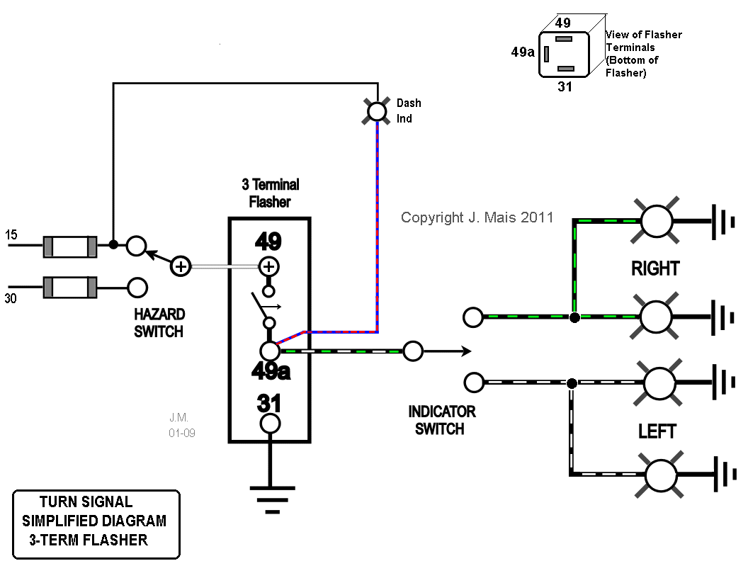
The flasher receives power from one of 2 fuses, depending on whether or not the Hazard switch is operated. The same flasher is used for both Turn Indicator and Hazard functions.
Internal circuitry in the flasher keeps a small "sense" voltage on Terminal #49a all the time. When the Indicator stalk is pulled to Left or Right, the Indicator bulbs on that side are connected to Terminal #49a and load the flasher circuit so that it knows to begin flashing. Immediately, the internal relay contact closes from (+) to #49a and the bulbs light. The flasher electronic circuit then turns the relay off and on to provide the flashing cycle.
The 4-terminal flasher has a built-in load sensing relay which drives the dash indicator. The dash indicator flashes in time with the Turn Indicator bulbs.
The dash speedo indicator bulb used with the 3-terminal flasher relay is connected from the (+) supply to #49a and it flashes opposite to the Turn Indicator bulbs. For example, when the Turn Indicator bulbs are lit, there is +12V present at #49a. That means that both sides of the dash bulb have +12V on them and no current can flow thru the bulb.
The only difference in circuit operation for Hazards is that the flasher receives power from the second fuse, which is live whether or not the Ignition is switched On or not. The Hazard switch has another set of contacts (not shown here) which connects both Left and Right sets of bulbs to the flasher.
Hazard Switch Operation with 3-wire Indicator switch
Later Beetles and Busses which had separate Stop and Turn lamps in the rear used a relatively simple Hazard switch arrangement. I've drawn it here in a form which shows the mechanical functioning of the switch contacts.
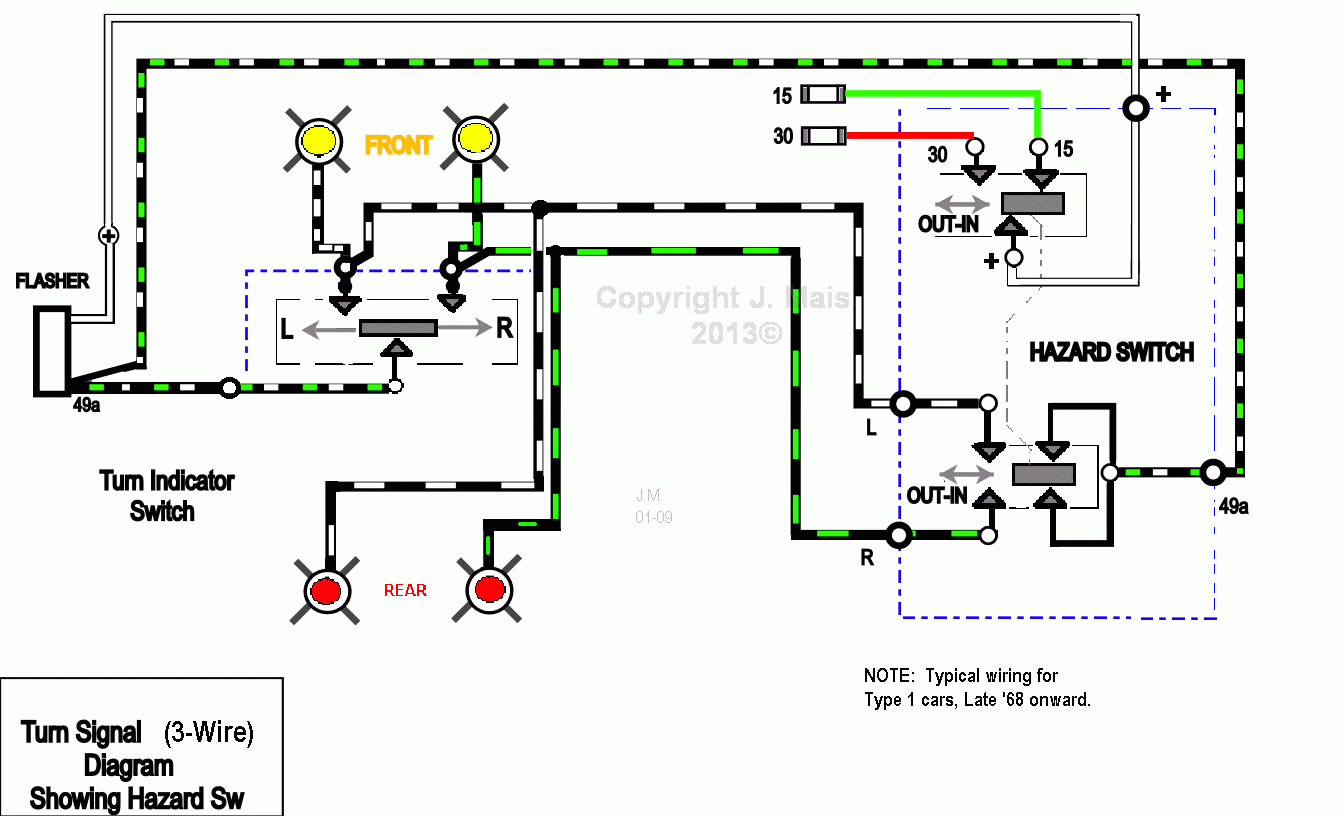
Here again, the Hazard switch selects the power source for the flasher from one of 2 fuses.
The lower switch section connects both Left and Right bulbs to Term #49a on the flasher so that all 4 bulbs flash.
6-Wire Indicator Switch
Now lets turn to the Turn Signal system used on early cars. From the mid 50's thru 1961, cars which did not have semaphores used the Stop lights to double as the rear Turn indicators. To do that, a special Turn Signal switch with 6 wires instead of the later 3-wire design was used. This switch had to route the flasher output to the Brake light being used for Turn indication while leaving the remaining Brake light to function from the Stop light switch. The circuit looks like this:
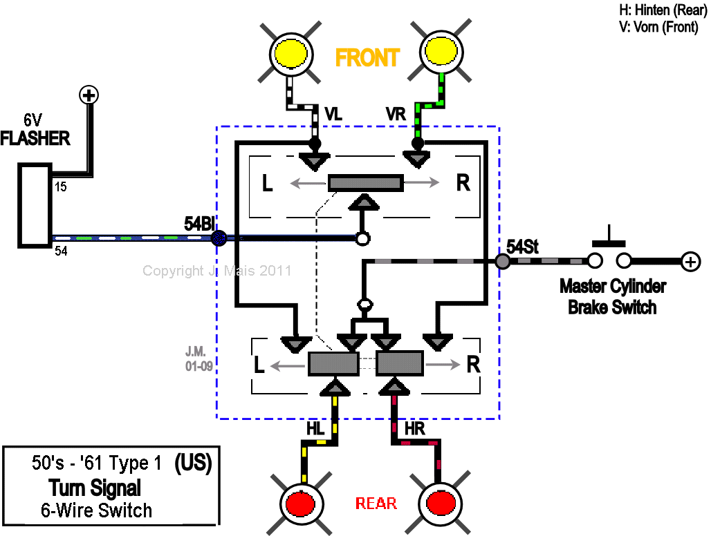
This arrangement was also used on (US) Busses all the
way thru the 1971 model.
Only in '72 did the US Bus get separate Stop and Turn bulbs.
![]() Click
here for the '68 thru '71 Bus wiring (very similar to above).
Click
here for the '68 thru '71 Bus wiring (very similar to above).
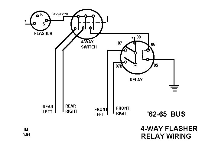
Early Bus Hazard wiring
'62 thru '65 models used a switch and a relay to provide 4-way flashing Hazard lights. The switch connected both rear lights to the flasher and simultaneously connected a relay to the flasher. The relay in turn powered both Left and Right front indicators from a separate fuse source. In other words, the relay switched on and off, in time with the flasher, thus flashing the front lights.
Greatly simplified, the circuit looks like:
From Late '68 thru '71, the 6-wire Turn indicator switch was married to a complicated Hazard switch in order to do away with the expensive 9-terminal flasher. The composite diagram is shown here:
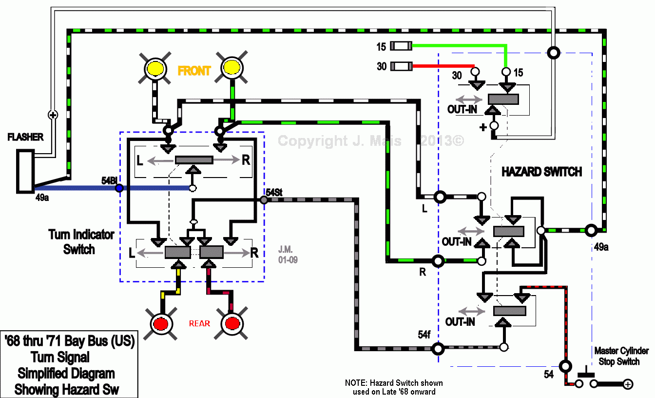
When the switch is pulled Out:
1) Power for the flasher is shifted from Term #15 to #30, which is live all the time.
2) Flasher Terminal #49a is connected to both Front Indicator lights.
3) The Stop light switch is disconnected from the rear lights and they are both connected to the flasher (via the Turn Indicator switch).
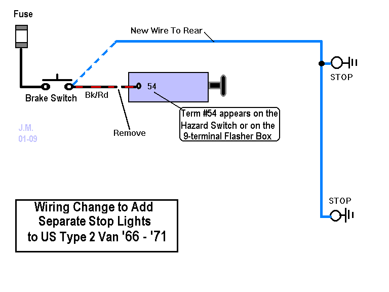
Converting early Bus (prior to '72) to have separate Stop and Turn lights.
US Busses from '66 thru '71 can be fitted with separate brake (or separate turn) lights with the addition of one wire to the Main harness going from front to rear. The Blk/Red wire from the master cylinder brake switch(es) must first be disconnected. This wire can be found on the 9-terminal flasher #54 or on the Hazard switch on later Busses which don't have the 9-terminal flasher. The new wire can then be spliced to the Blk/Red wire or connected right at the brake switch terminal. The wiring looks like this:
Flasher Internal Circuitry
For anyone interested in the detailed workings of the
flasher electronics,
I've included typical circuits from both the 4-terminal and 3-terminal
flashers.
Note that there were many variations on these designs over the
years,
these are just typical.
![]() 4-Terminal Flasher Circuit
4-Terminal Flasher Circuit