In cases where an engine oil temperature warning device (thermostat, Berg for example) is added the usual practice is to splice the thermostat wire to the oil sender wire so that either one will light the OIL light in the speedo.
That presents a problem in that the driver doesn't know whether the light is coming on due to (perhaps slight) overheating or due to complete loss of oil pressure. Clearly the latter situation deserves immediate attention.
To solve this dilemma, I came up with a simple circuit which will flash the OIL light when one of the contacts (pressure or temperature) closes. Thus, for example, a flashing OIL light means high oil temperature but a steady OIL light means loss of oil pressure.
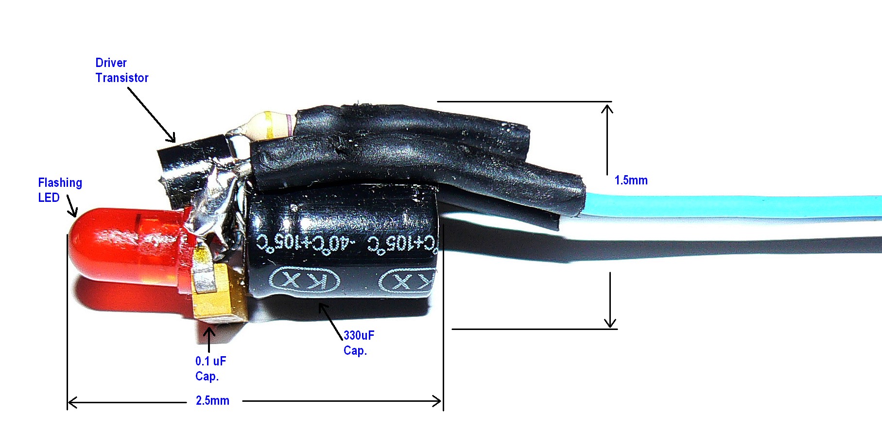
The circuit is shown here:
When the dipstick sender contact closes, current flows through the flashing LED and switches the driver transistor ON and OFF. The OIL light flashes at that rate.
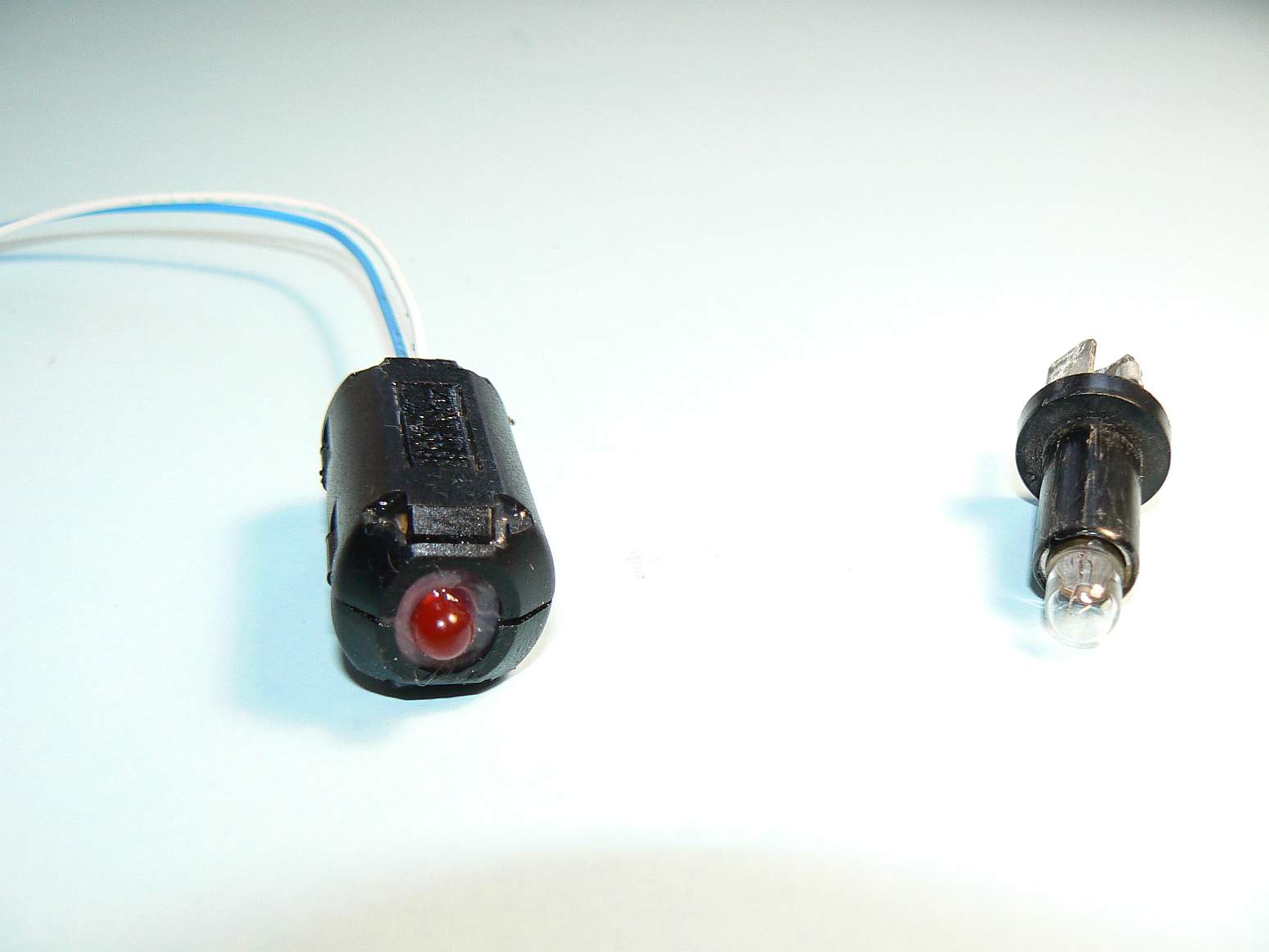
The circuit is easy to build and assembly is not critical. I squeezed the parts into a tubular housing with the LED poking out one end:
Feel free to build one on your own. The parts are readily available and not costly.
OTHER APPLICATIONS
A pesky problem which often arises is the need to install an additional wire in the main harness for either a tachometer or an oil temperature gauge. What if one of the existing wires could be made to "double duty", thus freeing up a wire for the accessory circuit.
The flasher might be used for this purpose. The following applies to Type 1 cars with an alternator with internal regulator and to Type 2 vans with any alternator. The flasher module is wired in the OIL sender circuit. The alternator D+ Lead is connected to the same bulb with a small diode inserted in the lead to block reverse current.
The dash light used will flash for loss of oil pressure and will be on steady for charging failure. This could be reversed if desired.
The wire which formerly went to the OIL sender (Blu/Grn) is now available for any other purpose.
CIRCUIT for ADDING TACHOMETER
The following shows how a tach can be installed without running extra wires to the engine. This section is unrelated to the flasher circuits above.
When the engine is running, the Blu/Grn OIL sender wire has +12V on it because the sender contact is OPEN. Suppose that we could force the voltage on that wire to go up to almost double the 12V every time that the points close. Then, at the dash end, retrieve those pulses without affecting the OIL warning light.
Briefly, the 0.1uF capacitor charges through the 1K resistor as shown. When the points close, the transistor turns ON and connects the lower end of the capacitor to the 12V supply from the Coil. For a short time, the voltage on the Blu/Grn sender wire leaps up to nearly 24V producing one pulse for each spark.
At the dash end, another capacitor strips off the +12V signal, leaving only the pulses to be sent to the tachometer.
This Web Page Created with PageBreeze Free HTML Editor